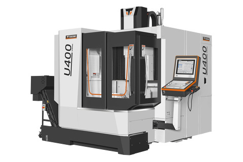
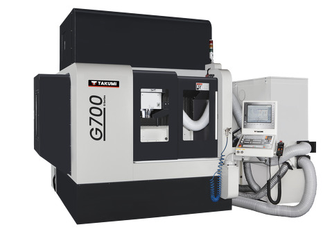
Choosing a 3 axis cnc milling machine starts with the parts you need to make, not the machine’s largest advertised numbers. A machine cutting aluminum brackets has different demands from one producing steel fixtures. Part size, material, tolerances, and expected production volume shape the right choice. Small errors in planning can become expensive.
Grand View Research valued the global CNC machine market at $101.22 billion in 2023 and forecast a 6.3% compound annual growth rate from 2024 to 2030. This broad market estimate signals continuing investment, but it does not tell you which mill suits your shop. That distinction matters. A market forecast is context, not a buying specification.
Begin with the work envelope, spindle speed, motor power, and tool capacity. Match those details to your actual materials and cutting tools. Then examine rigidity, positioning accuracy, controller usability, and service support. Ask for clear specifications and verify them with a representative test cut. A brochure cannot show every vibration, setup delay, or operator frustration. Some details only become obvious on the shop floor.
Also consider floor space, installation needs, training, maintenance, and the full cost of ownership. A low purchase price may conceal costly downtime or difficult support. Request references from users machining similar parts, and compare their experience with the supplier’s claims. Test cuts help, but one successful part is not proof of consistent production. Choose based on evidence you can check, while leaving room to reconsider assumptions that the first quote makes seem certain.
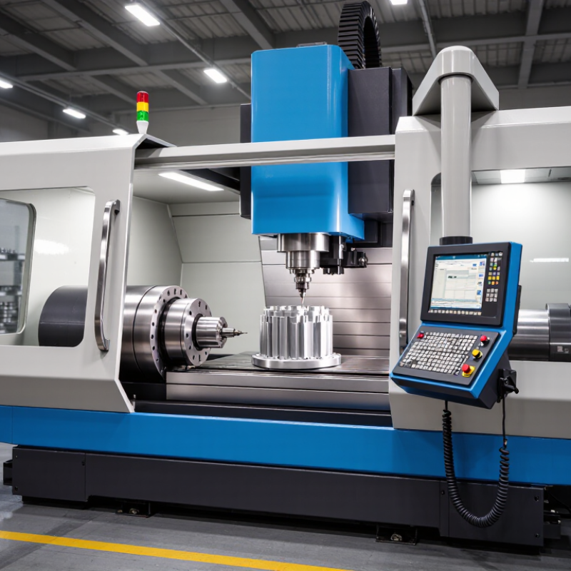
ISO 841 gives machine-tool axes a consistent reference, but their physical directions depend on the machine layout. The Z axis runs parallel to the principal spindle; its positive direction generally moves the tool away from the workpiece. X and Y complete the coordinate system, with positive directions following the right-hand rule. Do not assume X always means left-to-right. Check the machine’s axis diagram and documentation before comparing travel figures.
Set required X, Y, and Z travel from the largest planned part, not just its cutting path. Include the fixture, clamps, tool length, and room for safe approach and retraction. A vise may add several centimeters to the setup. Measure twice. Small errors matter. Then compare those needs with the machine’s usable travel, allowing clearance at each axis limit. Remember that a machine’s displayed axis motion may describe tool movement or workpiece movement; the resulting cutting relationship is what matters. A written travel envelope for your actual setup is a practical starting point, though estimates can miss awkward clamp positions. Recheck it with a representative part before committing.
An 8,000–12,000 rpm spindle suits many general-purpose VMC jobs, but the material and cutter diameter matter more than the headline speed. The standard cutting-speed equation in Machinery’s Handbook (31st edition) links surface speed, tool diameter, and RPM. For a 10 mm carbide cutter, a 300 m/min starting speed for aluminum works out to about 9,550 rpm. At 150 m/min for steel, the same cutter runs near 4,775 rpm.
These are planning examples, not universal settings; the ASM Handbook, Volume 16, also treats machining recommendations as dependent on material and tooling conditions.
Listen to the cut. A sharp, steady sound and even chips are useful clues; chatter, heat discoloration, or a squeal suggest reducing speed or checking tool stickout and rigidity. Small cutters need higher RPM to reach the same surface speed, while large cutters may exceed it quickly. That detail is easy to miss. If a machine’s spindle reaches 12,000 rpm, it does not mean every job should use it.
Start with the tooling maker’s cutting data, then adjust cautiously for coolant, workholding, and machine stiffness. Even careful calculations can be wrong at the first cut.
A 3-axis CNC milling machine’s spindle should match the materials, cutters, and duty cycle you expect to run. The 10–30 kW range is common, but the number alone does not predict cutting performance. A 10 kW spindle may suit smaller tools and lighter cuts, while higher power can help maintain material removal with larger cutters. Check the torque curve and rated power at your working speed, not only the peak rating. A machine can feel strong on paper and still struggle at low RPM. Not automatically.
BT40 is a widely used toolholding standard for general-purpose milling. It offers a practical balance of rigidity, tool size, and availability for many workshop jobs. Confirm the machine’s spindle interface and automatic tool changer accept the holders you plan to use. Also check toolholder condition, runout, balancing requirements, and maximum tool weight. Small runout can leave visible marks on a finished pocket, even when the program looks sound. Ask about the spindle’s cooling method and the recommended service interval; these details affect reliability over long shifts. I would compare a real cutting demonstration with your typical material and cutter. Spec sheets rarely show the whole story.
When comparing a 3-axis CNC milling machine, ask for positioning test results measured under ISO 230-2. The standard evaluates the positioning accuracy and repeatability of numerically controlled axes. Check X, Y, and Z separately, rather than relying on one overall figure.
Small errors matter. A few micrometres can affect hole spacing or the fit of a machined pocket.
Look for a report showing target positions, measured deviations, and approaches from both directions. A laser interferometer is commonly used, but the measurement setup and stated uncertainty matter too. Ask whether the machine was thermally stabilized and whether test conditions are recorded; temperature drift can change readings.
Repeatability tells you how consistently an axis returns to a position, while accuracy describes how closely it reaches the commanded one. Neither value alone predicts every cut.
ISO 230-2 axis tests do not fully describe three-axis movement together, spindle behavior, or performance under cutting load. That distinction is easy to overlook. Request a representative cutting test if your parts have tight tolerances, and compare its results with the axis report. A clean report is useful, but its limits deserve a closer look.
Check Table Load, Tool Capacity, and ATC Time Against Production Needs
Choose capacity around real jobs, not the largest part in your catalog. Add the workpiece, vise, fixture plate, and clamps when checking table load. A 180-kilogram part can become a much heavier setup. Confirm the machine’s rated load and table dimensions, then check whether the fixture blocks access to the spindle. Small details matter. Leave room for safe loading and chip removal.
Tool capacity should match the mix of operations in a typical shift. Count cutters, drills, probes, and spare tools that stay in the magazine. If operators change tools between jobs, a smaller magazine may be enough; if jobs run unattended, it may not. Ask for the stated automatic tool changer time and clarify whether it means tool-to-tool or chip-to-chip. Those figures describe different intervals.
Deloitte and MAPI’s 2023 Smart Manufacturing Survey found that 86% of surveyed manufacturing executives expected smart manufacturing to drive competitiveness within five years. That makes reliable cycle-time tracking useful, but it does not replace checking actual part programs and changeover needs.
Tips: Request a sample cycle-time estimate using your part, fixture, and tool list. Compare the stated ATC time with a real production sequence. I would verify this twice; catalog figures can hide setup delays.